Thursday, December 29, 2011

I Accidentally...

...my last urethane belt. Look at that snaggletooth.


As I began reassembling Razor Wind after cleaning it up, I neglected to check the motor direction before stepping outside for a test run. After the initial kick start, I threw the throttle only for it to instantaneously brake and change directions. Stripped all the teeth off.

Time to order the upgrades.

Also, I finally got the institute's mascot on my scooter. Been wanting this shot for years.


Sunday, December 25, 2011

Razor Wind: Shredding is a Pro for Guitarists, but not for Power Transmission

I've been running the Wheelpod system for about 3-4 weeks now and needless to say it has been an interesting experiment with pulley diameters and belt materials. I began with a 13T motor pulley, a 29T wheel pulley, and a 3/8" wide XL neoprene/fiberglass timing pulley. After a few runs, I noticed the drive producing extra grinding sounds and added a tensioner to absorb the thermally induced slack. Days later, the belt actually snapped.


All the teeth seemed to have rounded a bit (nominal trapezoidal shape) but the failure point was clear. The tension members all failed at one point, where the belt broke. At least I was in front of my apartment when it happened. Had I been at the Invention Studio, I might have been raging a bit.

So what happened? Easiest assumption is the wrong material. My second choice was a urethane belt, with kevlar tension member. Kevlar? HELLS YES! I also knew from experience that the urethane timing belts suffered less form expansion. I was hoping this combination alone would be able to solve my problems.

I did however have to change the motor pulley, because the Urethane belts came in intervals of 5 teeth (5 x .2" = 1" differences between belts) which meant I had to recalculate my belt distances. A new pulley with 11T was swapped for the 13T.

Can anyone guess what is going to happen next?

Well I blatantly ignored the minimum tooth requirement for most timing pulleys. Basically the number of teeth in contact with the motor pulley were not enough to resist the force required to move a human body at that ratio. Most (if not all the teeth) eventually sheered off like in the belt below.


And this belt too...


And this belt most recently. Luckily I had purchased enough belts to make it past my finals week (otherwise I would have surely been late to each one). The problem was clearly not belt or tension cord material. After consulting the problem from a few different angles I determined to cause to be the pulley diameter.


Increasing the pulley diameters (proportionally) would not change my overall ratio, but would allow a greater number of teeth in contact. This redistributes the sheer forces acting on each contact belt tooth.

While I was at it, I figured I would redesign the wheelpod chassis for 'real' belt lengths, and a dynamic belt tensioner.

However in the interest of saving time and material, I've elected to skip the experimental belt steps and revert to a method that has worked before: #25 chain. I will still be increasing the sprocket diameters to distribute the loads, but I will be using metal roller chain, which supports much higher working loads.

Starting with the largest motor side sprocket I could support and the center to center distance between the motor and wheel, I used this nifty chain length calculator to empirically determine a combination of chain and ratio that would suffice. The only limitations is that the sprocket tooth number and the # of chain links had to be integer values. In the end, I chose a 14T motor sprocket, 31T wheel sprocket, and a chain of 51 links. That gives an overall ratio higher than the current setup, but hell I know the motor can output enough power to make the scooter fly.

Machining to take place the moment I return to Tech. But until then, Happy Holidays!

Sunday, December 18, 2011

Razor Wind: Motorpod Edition

Shortly after the demonstration video shoot for the Clough Undergraduate Learning Commons, I burned out the version 1 wheelmotor. I knew the motor was running hot, I thought I had seen some sparks fly out the side, but I wasnt alarmed. Not until smoke billowed from the nearly air-tight electronics compartment was I actually worried.

Turns out some screws loosened, some wires shorted, and magnet wire combusted. Some serious weld marks were left inside my frame.

So I disassembled it and left it aside. I got pretty tired of fiddling with wheelmotors after rebuilding neumotor 2-3 times so I designed an alternate power system: The Wheelpod.

Behold!


A separate power drive system that easily slips into the space of the old one. This particular design slipped in between the two main frame rails and bolted/pivoted about the old wheel axle location. Mechanical tabs prevent the module from rotating in any undesirable direction. When a person stood on the scooter, the rotation about the pivot point applied a counter rotational force on the rear footrest spoiler and the from plate about the speed controller cover.

But what for drive? I spent a fair amount of time perusing the new line of Hobbything Turnigy SK3 motors when I realized Xo and I had one remaining unmodified Turnigy 6364-280 from Hardboard.

I never thought I would be reassembling one of those motors.

Some quick calculations: 280kv @ 22.2V, with 4" wheels and a ~2.2:1 belt ratio leaves about 30 MILES PER HOUR. YESSSSSSSSS!

The device went together about as quick as the waterjet could sneeze its watery sand snot.


Waterjet timing pulley using the low-taper cut settings to prevent belt deviations due to taper. The bore was turned to accept a giant-ass ball bearing. Eight holes run through the entire assembly to secure all parts.


 Wheels were also bored out. The preferred Colson 4" x 1.25" was selected because it offered the most thermoplastic core. The 1.5" and 2" wide versions has much more rubber and made turning difficult. For this design, I decided to enhance the rigidity of the wheel by adding aluminum plates to each side. This would give the bearings a better material to sit in and provide a more positive material to tap and thread.


The stack, not yet ready to be pressed in.


For some reason I managed to epically fail with hole placement. It did not occur to me the THRU diameter of #6 hardware, but I was left with this case regardless. So I did what any 'sensible' engineer would do and take a reamer to it. Don't hurt me too much.


The results were actually reasonable. It was very tight, but enough screws passed through to finish the piece. The way I see it, I have some potent 'thread locker' in this assembly. 


The protruding screws were screwed into the timing pulley above. After turning some spacers, boring out timing pulleys, and screwing stuff:


One thing I neglected to do was design the sensor module. As a result, it is currently running sensorless. While it is less a headache for me, I would like to someday add a data collection module in the scooter so I can produce REAL values for comparison. Someday...

Friday, October 14, 2011

This is the Remix

I actually began toying with this idea awhile back, but since Cake's drums have become worn I figured it was time to try it out.


The integrated brushless eggbeater.

I've generally kept away from it because the internals are essentially open and thus vulnerable to a direct hit. To ensure safety of my motor and electronics, the beater must spin fast and never stop. Those two terms became the primary focus points in a new revision of Cake, which I might end up giving a new name as there are enough changes to warrant a new design.

Besides, I could never supply a very good explanation of why it is named Cake. I guess that rules out Cupcake as a possible name.

I bought a new motor and battery from Hobbyking. A Turnigy 1450kv motor of the same stator size coupled with a 4-cell 1000mAh lipoly. This is a 350kv increase in motor, and 3.7v, 200mAh increase in battery spec. Expect longer runtimes and higher end rpms. No load (unrealistic) of ~21k rpms! Most other spinning weapons sit around 10k - 15k range, so I have no doubt I'll be spinning quicker than them. The exception of course are Gene and Richard's creations (~49k rpms?) so I'll have to design a strategy to fight those.


Here is the model. Already I am beginning to like this design because it addresses some of the complications I have found with the drum design. First, there are no endcaps. The beater is machined from a single piece of A2 tool steel, and thus has its endcaps permanently fixed to the knockers. Assembly of the motor will be more complex certainly, but I think the benefits outweigh the complications.


I hope to never need to machine another beater ever again. First, I rough cut the 1" block of steel on the waterjet leaving .01" on all edges. Then, I moved the block to the manual mill, squared all the edges,and removed the extra .01". Finally, I faced the beater. All operations probably totaled to 12 hours of work.

Worst yet, I managed to make 3 mistakes on the part. Good thing I am such a improvising badass. Can you spot the mistakes?


Rapid prototyping the magnet can mount. I blame Charles for this recent fascination in 3D printing. And before you ask, the answer is no. That part will not remain extruded ABS.


Speaking of rapid prototyping, what exactly are these?


These are the next set of bad ideas in this revision: Angled armor plates and isolated but integrated frame gearmotors. These ideas I've been designing since Attrition but never had the resources to implement it. Times ave changed. While the Dimension spat out the can mount, I had the uPrint mush out the angled mating blocks. The current plan is the remake them from aluminum but I have no patience and wanted to see it all together.


Bingo! Geometry test pass!

My next goals are to complete the drive system. Some minor complications for the moment: The battery supplied from Hobbyking is just a few unforeseen millimeters too wide. As a result, my Scorpion HX speed controller does not fit as intended. I may need to reinvest in single motor controllers and utilize the 45 degree drive method (Sans mixing). I've also noticed a large amount of frictional binding when the gearboxes are populated. Closer inspection showed the holes to be drilled at a slight angle. UGH! Should I continue with the B16 mod, I will have to bore out the holes to 9mm ON THE MILL for some flanged shielded ball bearings with a 4mm bore. Other alternatives are modifying the "1000 rpm motors" that everyone has been hyping about. I bought a pair (to arrive next week) and plan on swapping the motors out to the lower current drawing KW motors that normally come stock on the B16's.

Saturday, September 24, 2011

And We Shall Call it... Razor Wind

Last time we discussed the improvements over Safety Razor v1.1. Where are we now? Well in Atlanta Maker Faire build blitz, I built the entire thing. Lets see what images I can scrounge up.

Seeing as how there were 1-2 weeks until the event, I broke down construction into two main parts: frame and hubmotor. Ive attempted building a hubmotor several times, but never finished them. I'll be paying special attention to the motor this time.

First came the turning of the wheels. The front wheel included two facing operations and two counter boring operations for bearing recesses. The shaft was also turned from a round of 1-5/8" billet.


A stator was salvaged from a Turnigy motor. It measures 52.84mm in diameter and is planned for about 20-25 turns a tooth as described in the last post. The shaft was machined by our resident expert machinist Stephen Culpepper. A light application of glue held the motor in place.


Ever since I learned how to properly set my working zeros, my parts have come out drastically more precise with better finishes. The endcaps were First waterjet machined from 5/8" plate and then turned on the lathe. While mounting the plate on the cutting table, I realized I ordered 3" wide flat for a 3" dia part. 


Luckily, I am a boss. The advantage of waterjet cutting first allows me to add through holes and a tentative bore. This way, I wont have to mount the disks on a rotary table to drill the holes. 


Magnets installed. Each strip is actually composed of two magnets for a total of 28 magnets. It works, but is irritating for slow settling glue because the field on the edges repel each other.


I also spent this moment to waterjet the magnet flux rings. These were cut from 1/2" A-36 plate, epoxied together to make a total stack of 1.5". Anyway, back to the endcaps.


Partway complete.


These are probably the best pieces I have turned in my entire robotics career. The only surface I wish I could have treated were the outer edges of the flange as it still has the water jet's frosted edge.


Two endcaps with bearings were press fit in the bore of the wheel. Inside lay the waterjet style flux rings. A waterjet scrap of 3/32" polycarbonate served as a sensor mount. I figured this convenient in case I wanted to manually advance the timing of the motor.


Glued...


Wired...


Installed.

The rather large and wide front wheel of the scooter would need a custom set of front forks to account for the 2x width. Luckily, the Razor A2 frame has a "shock mounted front" aka block of rubber and hinge. I took this opportunity to create a custom mating piece that has shock absorption and a wider section. 


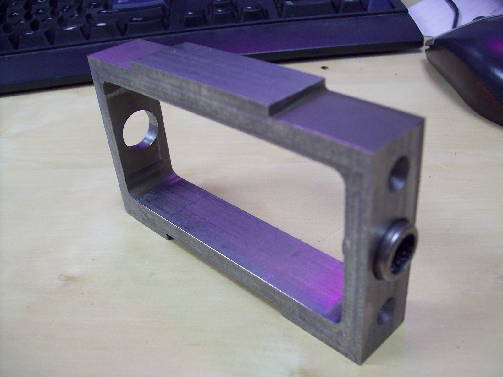
A block of aluminum was first water jet machined to rough dimensions and finished on the mill. The raised section in the back limits the backwards travel of the hinge, the 5/16" hole is the hinge point, and the 10-32 tapped holes mate to parallel plates to facilitate the wheel.


The frame went together as quickly and easily as the old one did. This time I spent time to open up the width of all the slots by .005" such that I would have to do less sanding later. I also decreased the kerf compensation from .015 to .012 on the waterjet. The combination of both along with the use of a scrapper produced a very clean tabbing. I don't have to hammer anything together, but instead they press lightly together. The appropriate frame parts were mill mounted and drilled as needed. First a spot drill, and then a sharp 3/32 to finish it up.

Repeat. The frame at one point in time looked like this:


The main rails were together and it was beginning to take shape. A day later:


It looks much more sleek than Safety Razor. Looking at it, you could barely tell it was electrically assisted at all. Let's compare it to Safety Razor:


By late Friday evening before the Maker Faire, the lot of us grew lazy. I was intending to waterjet the throttle pieces from 1/4" Aluminum, but Charles convinced me to start rapid prototyping the remaining parts.


 Among the throttle, the fan covers and charge plug covers were also printed.


The final product! Now presenting Razor Wind!


So how did it work? Well it worked well for about 20 minutes before failures began. The main problem lay in the motor. The motor seemed under specified for the amount of load required. I decided to opt for 20 turns of 20ga wire because I wanted speed, originally thinking the speed controller could throw enough current to through the motor to meet the requirements dictated by the sensors. However, this caused the motor to heat up very quickly. The heat, combined with the motor torque broke the glue joints and allowed the motor to rotate around the shaft. This effectively ripped wires apart internally and shorted some connections. The motor went up before the Maker Faire.

Razor Wind still served as a great display item along with the still functional Safety Razor. We also had some surprise scooter-wielding guests.


I have since then rewound the motor with 22ga wire and machined a small nail to act as a roll pin for mechanical locking. I am convinced the real solution would be to increase the voltage or overall size of the motor. My next solution, involves some number of these:


Monday, September 5, 2011

Dragon Con Bot Blitz

Dragon Con is (technically) still going on, and Robot Battles microbattles was yesterday. I already planned on bringing Cake and DDT, but Charles, Xo, Aaron, and I decided a fleet of "Assbots" were in order. By this time it was Friday the 2nd. Isn't Robot Battles on Sunday?

Charles was nice enough to donate an old Pop Quiz frame with some motors still attached. Remove weapon motor, blade, receiver and escs, as well as one motor. Three drive motors, a sturdy frame, and a dead 4-cell lipoly. This could work.

I left my shop camera at the apartment, but the result was pretty clear.


Introducing, Prop Quiz 0.5: waaaay too light.

Seriously, that is a 3 blade prop designed for baby helichoppers. Does it fly?


YES.

Unfortunately, it had some issues expressing flight in practice.


Xo and Aaron designed a melty style robot, where the entire frame rotates to give a 100% weapon mass.


And this is how that venture went:


Looks like it would have been pretty dangerous if it was made of metal or plastic and NOT WOOD. Seriously, the only piece of material we could find Saturday evening was a 3/4" block of wood. We decided to waterjet a pocketed frame that housed all the electronics. It also weighed approximately 1lb,5oz for a 3 pound class. I just wished it had hit the opponent instead of the wall.


And here is Charles' assbot, "$20,000 per year Enjeering Degree". Of course, the robot is in the arena, not the person on the left.


A resurrected sumobot back when speed hacked servos were still valid methods of power transmission. It also had a fair number of trinkets and symbolism: "the hand is symbolic of begging for money and the weight of student loans; the duct tape wrapped around the galvanized roof flashing is representative of the challenges students face in pursuit of fulfilling their engineering degree requirements; the threaded rod represents front-end ballast mass."

The serious business robots put on a great show as usual. DDT threw robot guts all about the arena and Cake probably threw a roof shot or two. Both robots were removed by Thomas Kenny's robots, who are great in design and quick as usual. The flaws in my robots were the same as usual, and I'll probably not fix them as well.

[rumble video]

So what's next? This upcoming Saturday is the Mini Maker Fair hosted by our very own Georgia Tech Invention Studio/Maker's Club. This means this week will be yet another hectic blitz to put together the scooter I hope to feature along with Charles' equipment. Be there if you can! We promise over 60 different exhibitors, a far greater turnout than expected.

Tuesday, August 16, 2011

Busy on Holiday

I'm currently on my two weeks holiday between work and institute but I'm kept relatively busy by upcoming events. Dragon Con and the Georgia Tech Mini Maker Faire are both coming up, which means I have about 5-6 things I need to get done.

Robots:
Running the bots at PA Bot Blast was a good way to test their metal against some real north east powerhouses but now I am left with no satisfactory running robots. Dragon Con doesn't run the 150 gram classes, but I still like to make a showing with an ant, beetle, and maybe a macro-class robot this year. I should have enough extra frame parts to revive Cake (I want to rebuild!) but the drums are just so fucked up I don't see too much in point in it. I would like to bring something different from DDT. The main idea is to not spend any extra money so we'll see how that turns out.

Costume(?):
If I go to any of these conventions, I like to put a little extra into it by dressing as something and then saving it for Halloween. As awesome as Tony Stark is, I DO NOT want to recycle a costume past a year. Hell, multiple conventions was pushing it. Right now I am looking into something Matrixy but those long coats are really damn expensive...

On to the interesting parts...

Scooter:
I bought this. Do I really need to state my intentions?


Safety Razor v1.1 is still in deployment, but I am putting foot down... on something other than concrete for braking. There are a few minor inconveniences in the current iteration that I am wanting to address in a new revision.
  • Braking - my left foot is unacceptable, and I just bought a pair of Nike shoes
  • Heft- At 13-15 pounds, the scooter weighs on the heavier side of objects. The motor alone weighs about 6 pounds, and the frame is unpocketed aluminum. All aspects of it (except the handlebars) are overspec'd.
  • Waterproof- it is not, and wetness has hurt it before
  • Switches - periodic replacement of switches due to destructive arcing is unacceptable. A precharge circuit is needed, or a high amperage switching method.
  • Longevity- last longer (she said that)
  • Smoother Rides- make it suck less when I hit cracks in the sidewalk
These are very realistic goals that all begin with the wheelmotor.

Weren't you building one already? Is it done yet? The answers to those questions are "yes" and "no". Since it isn't done yet, the logical thing would be to design another one.


In reality, I have an issue with leaving proper amounts of space for wires. I wish they were of infinitesimal thickness. Besides, that version was fitted to a 5" wheel, and as my calculations show, I can get a more efficient package from a smaller diameter but wider wheel (assuming stator also follows).


The new wheelmotor plan has lots of space for wires to route (over 1/4" of room) and a beefy 3/4" shaft for the passage of wires. The stator comes from a Turnigy motor, has a diameter of 52mm, and a length of 30mm. The stator will be wound dLRK with ~25 winds per tooth. Each magnetic pole is composed of two N52 neodymium bar magnets. All of this will be captive in a 4" rubber wheel of 40A durometer. Air gap is currently 0.6mm ideal.


To make this motor comparable to the 400W Kollemorgen , I will be routing sensors through the motor. A tad bit of trial/error is involved because I am planning on using a 150A RC car esc to drive it. Thanks to Charles and Shane, I have the pinouts of the sensor cables but I'll still be playing the mix 'n match game to determine the "A", "B", "C" motor terminals.


As a result of the motor swap, the entire frame gets a redux. The frame rails are still Aluminum but only 19" long now, and 3/16" thick instead of 1/4" before. In fact, all 1/4" plate is changed to 3/16". The top and bottom plates are still 1/8" Al, but there is no longer a garolite fancy cover plate. Instead, I am going to try engraving on some skater's grip tape and stick that to the aluminum. Also notice there are no T-nuts. All holes will be mill drilled and a silicon caulking will be applied to the inside corners to help with waterproofing.


Why don't I need the garolite cover anymore? All charge plugs are now externally accessible. A simple cover will go on top of those to prevent crud from getting inside.

What on earth is that monstrous black tumor protruding from the back? That is the model of the 150A esc. I don't actually have it on my persons yet.

Meanwhile, the battery was upgraded to a 6s1p 5000mAh lipoly pack. Super longpak!


A slight modification to the front forks to make it look less... awkward. This is the true advantage of the Razor A2 or A3 scooters.

For now, this will sit under the Safety Razor tag, but I am open to new names. Razor Wind?